BConnect – an expansion concept for building complex systems in tiny spaces.
Introduction
The BConnect (Bus Connect) concept is a spin off from the existing Groove, Stemma and Qwiic where we instead of a bulky connector and cables use an FFC (Flexible Flat Cable) and a tiny flexible flat cable connector to do the job. This means that we can get away with connectors that have 0.5mm pitch which makes them super small.
In the BConnect concept there are three main buses that have been implemented and are (will be) supported.
- I2C (Bi2C)
- UART (Bserial)
- SPI (BSpi)
The Bi2C bus have been implemented and supported for some time. It is well proven and works great with the different accessories that are available. The BSerial interface have just recently been introduced with the BSerial WiFi/BLE product. At the time of this writing there are no current products available with the BSpi interface.
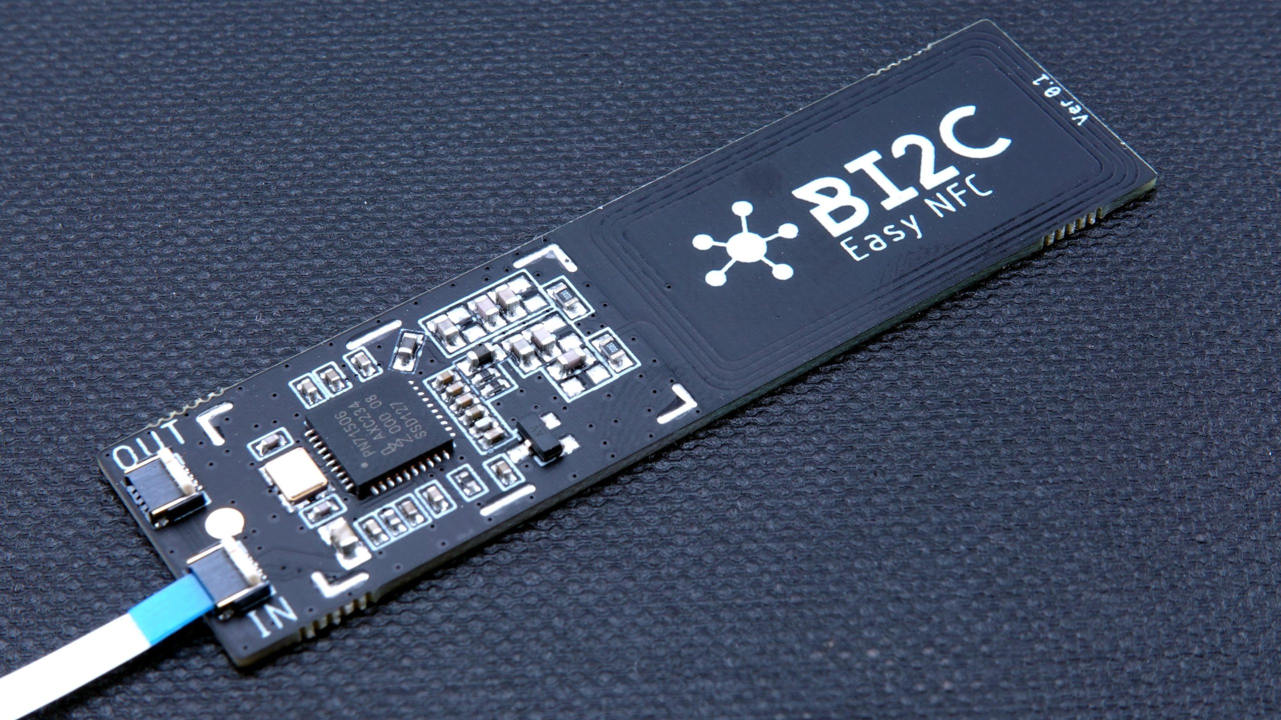
The BI2C interface differs from the Groove, Stemma and Qwiic versions in that its connections goes straight through the cable as opposed to Groove/Stemma/Qwiic cables that are reversed between the two connectors. This means that there is a difference between OUT going connector (Source) and IN coming connector (Sink). These are clearly marked on each board such as on the board in the first picture. So in the most simple scenario you would connect the Bi2C connector on the MCU board to the “IN” connector on the Bi2C board.
The same applies to the BSerial interface although as this is a point to point interface BSerial devices does not have an OUT connector which makes it less of a problem when connecting boards together.
Most Bi2C boards (but not all) will have an OUT connector that allows you to daisy chain multiple boards allowing very complex systems to be built with minimal effort.

Within the BConnect concept we have currently defined two different pin-outs for the interconnect. These connectors apply to the Bi2C and BSerial interfaces. The BSpi has yet to be defined.
One 4-pin connector and one 6-pin connector have been defined with the following pin-outs:
For Bi2C
| Source Connector (OUT) | Sink Connector (IN) | ||
| Pin no | Name (Function) | Pin no | Name (Function) |
| 1 | SCL | 1 | GND |
| 2 | SDA | 2 | +3V3 |
| 3 | +3V3 | 3 | SDA |
| 4 | GND | 4 | SCL |
For BSerial
| Source Connector (OUT) | Sink Connector (IN) | ||
| Pin no | Name (Function) | Pin no | Name (Function) |
| 1 | RXD | 1 | GND |
| 2 | TXD | 2 | +3V3 |
| 3 | +3V3 | 3 | TXD |
| 4 | GND | 4 | RXD |
For Bi2C
| Source Connector (OUT) | Sink Connector | ||
| Pin number | Name (Function) | Pin number | Name (Function) |
| 1 | GPIO 1 | 1 | GND |
| 2 | GPIO 2 | 2 | +3V3 |
| 3 | SCL | 3 | SDA |
| 4 | SDA | 4 | SCL |
| 5 | +3V3 | 5 | GPIO 2 |
| 6 | GND | 6 | GPIO 1 |
For BSerial
| Source Connector (OUT) | Sink Connector | ||
| Pin number | Name (Function) | Pin number | Name (Function) |
| 1 | GPIO 1 | 1 | GND |
| 2 | GPIO 2 | 2 | +3V3 |
| 3 | RXD | 3 | TXD |
| 4 | TXD | 4 | RXD |
| 5 | +3V3 | 5 | GPIO 2 |
| 6 | GND | 6 | GPIO 1 |
The extra GPIO pins of the 6pin connector can be used to transport an interrupt signal, a reset signal or basically any other type of GPIO signal that the BConnect module requires. These signals should always be connected to GPIO signals on the MCU board to allow full functionality. When designing a board that uses the BConnect system you need make room for the FFC to enter the board and make its way to the connector.
The MCU boards
Below is an example of one of our own boards implementing the BConnect-4 interface. This is the Challenger NB RP2040 WiFi board which has the BConnect connector a little below the USB connector. The connector is placed a small distance from the pin header row allowing the FFC (Flexible Flat Cable) when bent a little upward to fit in there properly.

Power
The BConnect system is not designed to carry a lot of current and we have specified the system to no more than 250mA on one string of Bi2C devices. A few, but not all, of our own Challenger boards have a dedicated LDO for the Bi2C connector and they are rated at 250mA so if you connect units that consumes more than the 250mA the system will fail. Often failing very erratic making it hard to trouble shoot.
The power line (+3V3) must always be +3.3V (± 5%) and any Bi2C modules that require other voltages must have connectors or points where this supply voltage can be connected to.
Flexible Flat Cables
The cables used are 0.5mm pitch FFC’s adapted to fit the PCB FFC connector well. These cables are available in different lengths, currently 10cm, 20cm and 30cm cables are available.
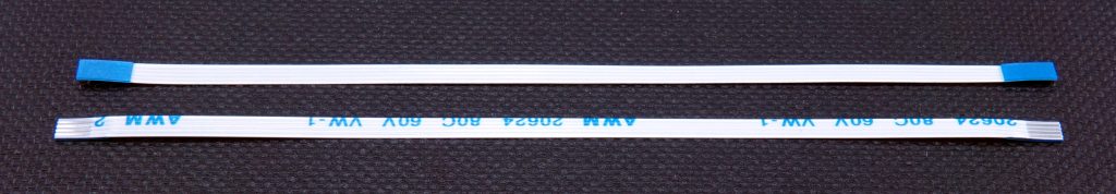
The cables can be bent sharply into position at least once, maybe twice but after that they can break when re bending them.
The length also affects both the noise immunity and the emitted noise from the cable. Care should be taken when using the very long cables to make sure that everything is within specified levels. For instance, it is maybe not a good idea to run a High Speed (3.4MHz) I2C interface over a 30cm cable without taking extra shielding precautions.
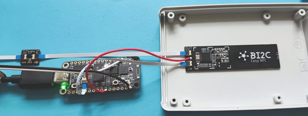
Example
Below is an image of an experimental system using a Bi2C NFC reader module and an accelerometer. We’ve used this to create a proof of concept for the Bi2C modular system.