Challenger 840 BLE – 2/4/8 MB Datasheet
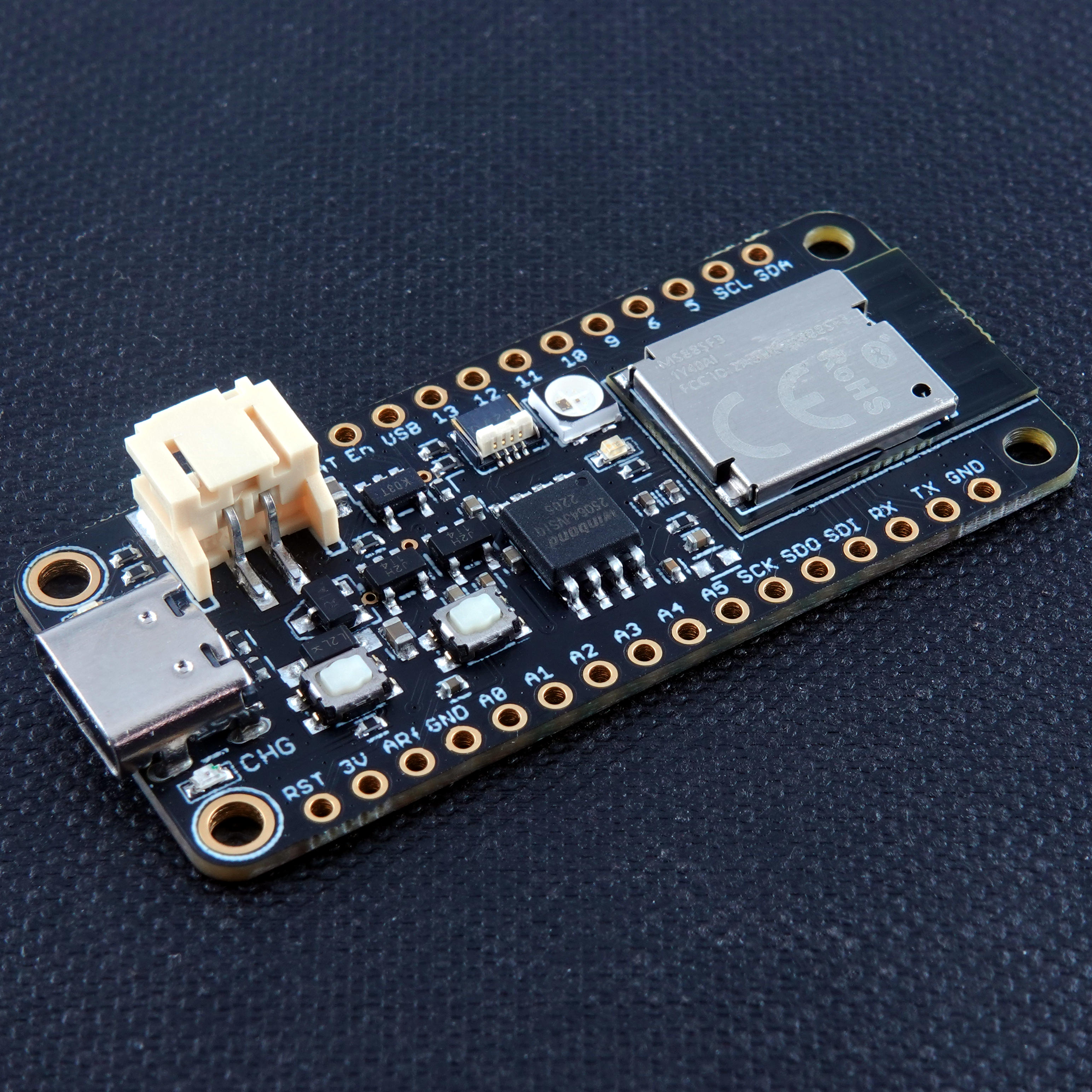
The Challenger 840 BLE is a small embedded computer equipped with a fully integrated BLE module based on the nRF52840 MCU from Nordic Semiconductor.
The board is in the popular Adafruit Feather form factor with the nRF52840 MCU being a 64MHz ARM Cortex M4 based micro controller with an integrated 2.4GHz radio suitable for bluetooth, BLE and many other radio standards.
For more in depth information about the nRF52840 you can look here.
The nRF52840 MCU is in itself very impressive but we wanted to add a few features to create a useful little module that can be used in all sorts of applications and of course we wanted it to support Circuitpython for all of you fan boyz playing along at home.
We also wanted to make it super low power so you could run it for ever on a battery so we used the lowest Iq LDO that we could find and at ~1.5uA you will struggle to find a better solution.
The device can be powered from a Lithium Polymer battery connected through a standard 2.0mm connector on the side of the board. An internal battery charging circuit allows you to charge your battery safely and quickly. The device is shipped with a programming resistor that sets the charging current to ~500 mA. this resistor can be exchanged by the user to either increase or decrease the charging current, depending on the battery that is being used.
Short introduction to the board
PCB
The board is based on a popular form factor called “Feather” which is created and maintained by an American company called Adafruit. The entire specification for the Feather format is available here. The size of the PCB for the module is 50.80mm x 22.86mm but the entire module is a little bit bigger as the Type C USB connector protrudes about 1 mm outside the board.
Antenna
On the opposite end from the USB connector the you will find the antenna. This is an integrated meandered planar inverted-F antenna (PIFA) and as always you should keep it away as far as possible from enclosure walls, wires running in the enclosure and big ground planes.
Headers
On each of the longer sides of the PCB there are holes intended for soldering pin header connectors. If you don’t want to use connectors for some reason you can also solder a wire directly into the hole, making a permanent connection to your external device. If you go this way please make sure that the wires are fixed in place, otherwise vibrations can cause the wire to brake at the soldering point.
LED’s
On each side of the USB connector there is a small indicator LED placed. The LED which is marked CHG is the charge control indicator. This red LED will shine red whenever the connected battery is being charged, and when the battery is fully charged the LED will turn off again. If you haven’t connected a battery to the board this LED will not come on at all.
We’ve also included two more user programmable LED’s on the board. These are called LED_GREEN and LED_BLUE. These LED’s can be programmed using the standard gpio commands in the Arduino environment as well as in the Circuitpython environment.
  pinMode(LED_GREEN, OUTPUT);
  digitalWrite(LED_GREEN, HIGH); // Green LED on
  digitalWrite(LED_GREEN, LOW); // Green LED off

  pinMode(LED_BLUE, OUTPUT);
  digitalWrite(LED_BLUE, HIGH); // Blue LED on
  digitalWrite(LED_BLUE, LOW); // Blue LED off
The blue LED is also used by the boot loader to indicate when it has been engaged and when there is data being sent.
We’ve also included a fancy schmanzy neopixel LED just beside the BLE module, just so you can produce any personal color you’d like as an indicator. Getting this LED going is as easy as:
#include <Adafruit_NeoPixel.h>

// When setting up the NeoPixel library, we tell it how many pixels,
// and which pin to use to send signals.
Adafruit_NeoPixel pixels(1, LED_NEOPIXEL, NEO_GRB + NEO_KHZ800);

uint8_t colors[3][3] ={ { 15, 0, 0 }, { 0, 10, 0 }, { 0, 0, 20 }};

void setup() {
  pixels.begin(); // INITIALIZE NeoPixel object (REQUIRED)
}

void loop() {
  static int i = 0;

  pixels.clear(); // Set all pixel colors to 'off'
  pixels.setPixelColor(0, pixels.Color(colors[i][0], colors[i][1], colors[i][2]));
  pixels.show();   // Send the updated pixel colors to the hardware.

  if (++i == 3) i = 0;

  delay(500);
}
Buttons
There are 2 buttons on the board. One RESET button (close to the USB connector) and one BOOT loader button (close to the flash memory chip).
The RESET button is obvious, it will cause the nRF52840 to reset and restart the system, which is what you would expect of a reset button =). The BOOT button is not as obvious. In normal usage it is a user programmable button that you can use for your own purpose. No strings attached.
BUT !, During boot this button is also being used to detect if you as a user want to take the system into boot loader mode. This is extremely useful if you’ve made something to the system that causes it to not to initialize the USB channel. In this case you can press the BOOT button while pressing RESET and the system will move into a state where you can upload new software. Very handy, I know =)
Hardware details
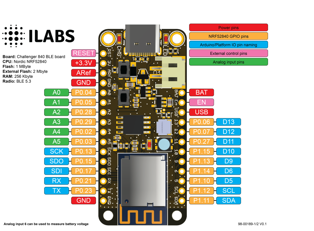
Pins
The on board micro controller have a number of communication channels that have been routed out to the side (header connector) connectors.
- UART – One UART channel have been routed to the header pins (RX, TX).
- SPI – One SPI channel have been routed to the header pins (SCK, SDO, SDI)
- I2C – One I2C channel have been routed to the header pins (SCL, SDA).
- Analog pins – The micro controller have 6 analog input pins that all are available on the header pins (A0-A5).
- PWM – All pins can be used for PWM.
The pin chart below shows the placement of all pins and their respective functions.
Power
The board can be powered from multiple sources. The most obvious way to run the board is by plugging it in to a USB cable and attach it to your computer. In this mode you can write software and test the board with all its functionality.
Secondly you can power the board by applying a 3.7V – 5.5V source on the pin marked USB on the right row of connector holes on the pin diagram. This will allow the system to run even when the USB cable is not inserted. Make sure you connect your voltage source through a diode capable of handling at least 500mA. Otherwise there will be a conflict between the USB cable and your power source.
There is also a third way to supply the board. This way is more invasive and will disable the onboard 3.3V power regulator.
You will have to pull the EN header pin low and then supply your own 3.3V voltage on the 3.3V header pin. Please note that when disabling the onboard power regulator you will have to supply the 3.3V also when running the system on battery power.
Lastly the system can also be powered from a battery which is described in the chapter below.
Battery
As described earlier the board can be powered from a LiPo battery. The battery can be connected using a standard 2-pin 2.0mm JST PH connector through the battery connector on the right side of the board or ff the battery is an integral part of the system that you are designing it is possible to connect the battery through the BAT pin instead.
Switching between the battery voltage and the applied USB voltage or external 5V is done seamlessly by the on board circuitry.
Charging of the battery is done by either connecting a USB cable or by connecting a 5V power source to the header pin marked USB on the board.
Please note that providing external charger circuitry could destroy the internal charger on the Challenger board.
There is also circuitry available on the board to measure the battery voltage. This is done by taking the battery voltage and feeding it through a resistor divider and then in to the ADC of the Nordic chip. Here’s a short example on how to read the battery voltage:
#include <bluefruit.h>

// Convert from adc value to battery voltage.
// Times 2 because the resistor divider divides by 2.
#define VAL2VOLT(x)   (3.0 / 1024.0 * x * 2)

void setup() {
  // Set internal analog reference to 3.0V
  analogReference(AR_INTERNAL_3_0);
  // Use 10 bits resolution
  analogReadResolution(10);

  while(!Serial)
    delay(100);
  Serial.begin(115200);
}

void loop() {
  // Read out battery and supply voltage
  Serial.print("Battery voltage: ");
  Serial.println(VAL2VOLT(analogRead(PIN_VBAT)));

  delay(1000);
}
Please remember that as long as the device is plugged in with the USB cable and/or being fed 5V externally you will only be seeing the charge voltage here. To be able to read the actual battery voltage you need to unplug the USB cable and/or the external 5V supply.
On Board FLASH memory
The board is equipped with a 2 MByte, 4 MByte or 8 MByte (Depending on the model you buy) external serial FLASH memory that allows you to create file systems, use as bulk storage or even as a disk drive where you store your python programs.
The provided Arduino framework contains support for using this memory together with the AdaFruit FlashSPI library which allows you to handle the flash memory as an internal file system. Check out the example below on how simple it is to print the contents of an existing file:
// Adafruit SPI Flash FatFs Simple Datalogging Example
// Author: Tony DiCola

#include <SPI.h>
#include <SdFat.h>
#include <Adafruit_SPIFlash.h>

Adafruit_FlashTransport_SPI flashTransport(EXTERNAL_FLASH_USE_CS,
                                           EXTERNAL_FLASH_USE_SPI);
Adafruit_SPIFlash flash(&flashTransport);
FatVolume fatfs;

// Configuration for the file to open and read:
#define FILE_NAME      "test2.txt"

void setup() {
  // Initialize serial port and wait for it to open before continuing.
  Serial.begin(115200);
  while (!Serial) {
    delay(100);
  }
  Serial.println("Adafruit SPI Flash FatFs Simple File Printing Example");

  // Initialize flash library and check its chip ID.
  if (!flash.begin()) {
    Serial.println("Error, failed to initialize flash chip!");
    while(1) delay(1);
  }
  Serial.print("Flash chip JEDEC ID: 0x"); Serial.println(flash.getJEDECID(), HEX);

  // First call begin to mount the filesystem.  Check that it returns true
  // to make sure the filesystem was mounted.
  if (!fatfs.begin(&flash)) {
    Serial.println("Error, failed to mount newly formatted filesystem!");
    Serial.println("Was the flash chip formatted with the fatfs_format example?");
    while(1) delay(1);
  }
  Serial.println("Mounted filesystem!");

  // Open the file for reading and check that it was successfully opened.
  // The FILE_READ mode will open the file for reading.
  File32 dataFile = fatfs.open(FILE_NAME, FILE_READ);
  if (dataFile) {
    // File was opened, now print out data character by character until at the
    // end of the file.
    Serial.println("Opened file, printing contents below:");
    while (dataFile.available()) {
      // Use the read function to read the next character.
      // You can alternatively use other functions like readUntil, readString, etc.
      // See the fatfs_full_usage example for more details.
      char c = dataFile.read();
      Serial.print(c);
    }
  }
  else {
    Serial.print("Failed to open file \"");
    Serial.print(FILE_NAME);
    Serial.print("\" !! Does it exist?");
  }
}

void loop() {
  // Nothing to do in main loop.
  delay(100);
}
Make sure you have selected the correct flash size for your board in the Tools menu in the Arduino IDE before downloading the code.
Low power consideration
Arduino
The Challenger 840 BLE board comes well prepared to be very power efficient. As such we have provided a means of disconnecting the power to the RGB LED as well as the Bi2C connector. The RGB LED and the Bi2C connector runs on it very own LDO (Low Drop Out regulator) which can be turned on and off by toggling a GPIO pin.
In the arduino environment this pin is by default set to high by the framework, this enabling the LDO and having the system fully up and running from the start. If you need to shut the LDO down this can very easily be done by running the following:
digitalWrite(PIN_LDO_CONTROL, LOW);The pin has previously already been configured to be an output pin by the framework, so no need to worry about that.
Circuitpython
In circuitpython the LDO is not turned on by default, instead this has to be done explicitly, for each application that needs the RGB LED and the Bi2C connector.
In Circuitpython then you would do something like this:
ldo_pin = digitalio.DigitalInOut(board.LDO_CONTROL)
ldo_pin.direction = digitalio.Direction.OUTPUT
ldo_pin.value = 0  # Turn LDO off
ldo_pin.value = 1 # Turn LDO on| Description | Value | Comment |
|---|---|---|
| Board Size | 50,80 mm x 22,86 mm x 3,20 mm | USB Connector protrudes ~1mm outside PCB |
| Main micro controller | nRF52840 from Nordic Semi | 64MHz Cortex M4 with FPU |
| SPI | One SPI channels configured | |
| I2C | One I2C channel configured | |
| UART | One UART channel configured | |
| Analog inputs | 6 analog input channels | |
| Radio functions | Bluetooth Low Energy, Bluetooth mesh ANT, 802.15.4, Thread, Zigbee | |
| FLASH Memory | 1MByte | |
| External FLASH Memory | 2MByte, 4MByte or 8Mbyte | |
| SRAM Memory | 256KByte | |
| USB 2.0 controller | Up to 12MBit/s full speed | Integrated USB 1.1 PHY |
| JST Battery connector | 2.0mm pitch | |
| On board LiPo charger | 500 mA nominal charge current |