Challenger RP2040 SD/RTC Datasheet
The Challenger RP2040 SD/RTC is a small embedded computer equipped with a micro SD card reader as well as a Real Time Clock (RTC), in the popular Adafruit Feather form factor. It is based on an RP2040 micro controller chip from the Raspberry Pi foundation which is a dual core Cortex M0 that can run on a clock up to 133MHz.
For more information about the RP2040 you can look here.
We paired the RP2040 micro controller with a 8MByte high speed flash capable of supplying data up to the max speed. The flash memory can be used both to store instructions for the micro controller as well as data in a file system and having a file system available makes it easy to store data in a structured and easy to program approach.
The embedded micro SD card reader can be used to store huge amounts of data, great for those logging applications where you need to catch all that important sensor data.
Coupled with that we also included a real time clock (RTC) circuit on board that will allow you to capture the exact time that data came in. Connect a RTC-backup battery and you never have to worry about time any more =)

Short introduction to the board
PCB
The board is based on a popular form factor called “Feather” which is created and maintained by an American company called Adafruit. The entire specification for the Feather format is available here. The size of the PCB for the module is 50.80mm x 22.86mm but the entire module is a little bit bigger as the Type C USB connector protrudes about 1 mm outside the board.
Micro SD card reader
The micro SD card reader is located on the opposite end of the board from the USB-C connector. The reader accepts standard micro SD cards and so far we haven’t found a card that doesn’t work with our board. The card is inserted into the connector parallel to the board. It should be inserted firmly (but not to hard) to make sure that the detect switch is closed.
Real time clock (RTC)
The board has an on board real time clock connected to the common I2C bus. The device used is microchip MCP79410 that can provide very high accuracy, with internal trimming registers, if required.
Headers
On each of the longer sides of the PCB there are holes intended for soldering pin header connectors. If you don’t want to use connectors for some reason you can also solder a wire directly into the hole, making a permanent connection to your external device. If you go this way please make sure that the wires are fixed in place, otherwise vibrations can cause the wire to brake at the soldering point.
LED’s
On each side of the USB connector there is a small indicator LED placed. The LED which is marked CHG is the charge control indicator. This red LED will shine whenever the connected battery is being charged, and when the battery is fully charged the LED will turn off again. If you haven’t connected a battery to the board this LED will not come on at all.
On the other side of the USB connector there is a user programmable green LED. This LED is connected to pin D18 and can easily be controlled by the user program.
Hardware details
External pins
The on board micro controller (RP2040) have a number of communication channels that have been routed out to the side (header connector) connectors.
- UART – One UART (UART1) channel have been routed to the header pins (RX, TX).
- SPI – One SPI (SPI1) channel have been routed to the header pins (SCK, SDO, SDI).
- I2C – One I2C (WIRE1) channel have been routed to the header pins (SCL, SDA).
- Analog pins – The micro controller have 4 analog input pins that all are available on the header pins (A0-A3).
- PWM – All pins can be used for PWM.
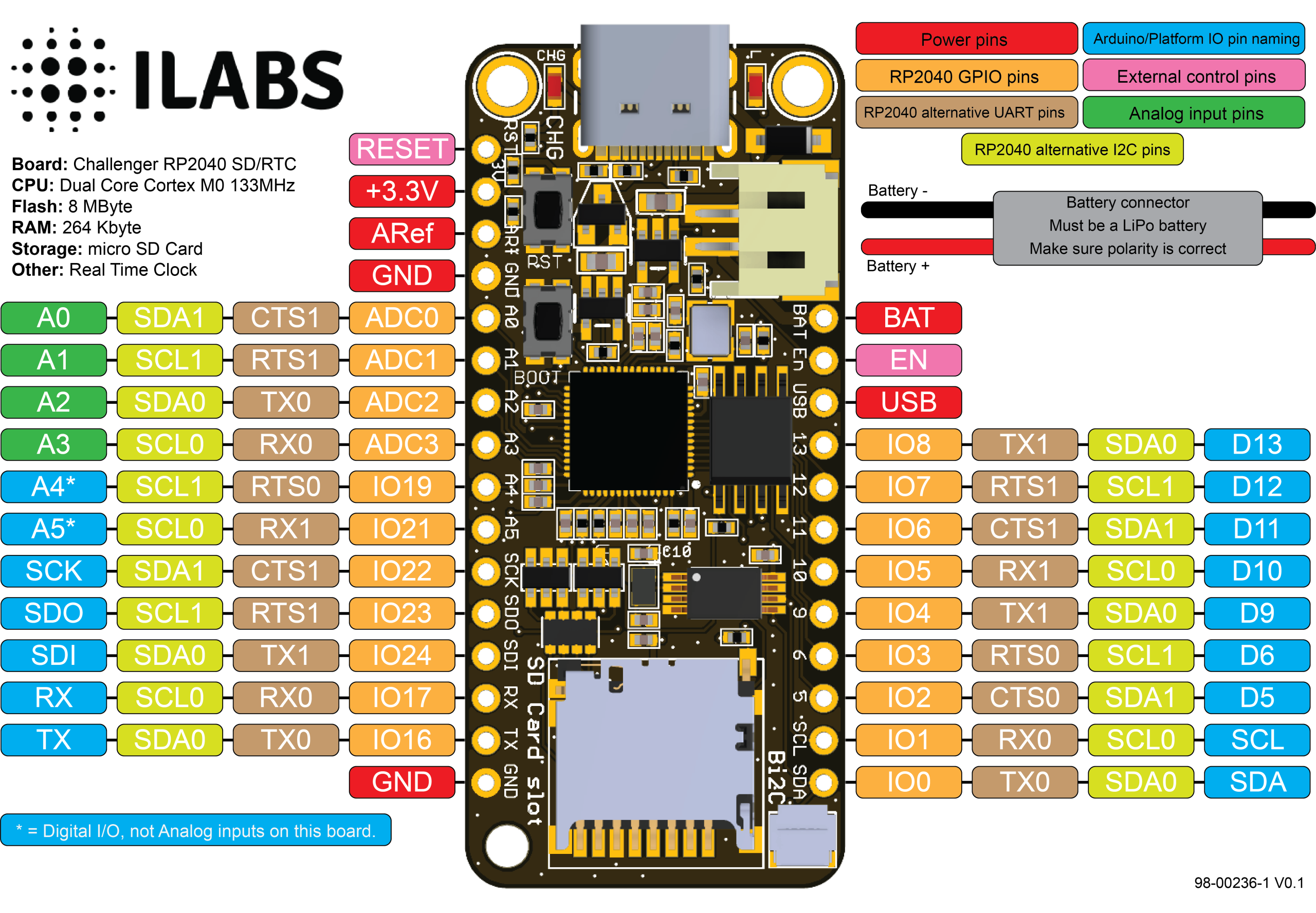
The pin chart below shows the placement of all pins and their respective functions. When working in an Arduino environment (or Platform IO) use the blue pins when writing your code and when working with CircuitPython use the orange marked pin assignments.
Power
The board can be powered from multiple sources. The most obvious way to run the board is by plugging it in to a USB cable and attach it to your computer. In this mode you can write software and test the board with all its functionality.
There is also a third way to supply the board. This way is more invasive and will disable the onboard 3.3V power regulator.
You will have to pull the EN header pin low and then supply your own 3.3V voltage on the 3.3V header pin. Please note that when disabling the onboard power regulator you will have to supply the 3.3V also when running the system on battery power.
Battery
As described earlier the board can be powered from a LiPo battery. The battery can be connected using a standard 2.0mm JST connector through the battery connector on the right side of the board or ff the battery is an integral part of the system that you are designing it is possible to connect the battery through the BAT pin instead.
Switching between the battery voltage and the applied USB voltage or external 5V is done seamlessly by the on board circuitry.
Charging of the battery is done by either connecting a USB cable or by connecting a 5V power source to the header pin marked USB on the board. If you do this make sure you connect your voltage through a 1A schottky diode to avoid any excessive current draw in the system when the two levels are slightly different.
Please note that providing external charger circuitry could destroy the internal charger on the Challenger board.
RP2040 SD Card connector
Connection between MCU and the SD card.
The processor connects to the SD card via the second spi (SPI1) communication channel.
SPI1 Pin usage:
- GPIO10 is the serial clock (SCK)
- GPIO12 is the serial data input (SDI)
- GPIO11 is the serial data output (SDO)
- GPIO9 is the SD Card chip select signal (#CS)
In addition to the described signals a card detect signal is also connected to the connector. When this signal is logically low a card has been inserted and when it is high the card has been removed.
- D14/GPIO13 card detect (Has a weak external pull (220K) up for low power consumption).
The Circuitpython image comes with the SD card driver library pre-installed, ready to run. In order to run any examples it is important that the spi bus (SPI1) is configured properly. The following piece of code will initialize the system properly and list any files on the SD card.
import os
import board
import busio
import storage
import digitalio
import adafruit_sdcard

spi = busio.SPI(board.SD_SCK, board.SD_SDO, board.SD_SDI)
cs = digitalio.DigitalInOut(board.SD_CS)
sdcard = adafruit_sdcard.SDCard(spi, cs)
vfs = storage.VfsFat(sdcard)
storage.mount(vfs, "/sd")

# Use the filesystem as normal! Our files are under /sd

# This helper function will print the contents of the SD
def print_directory(path, tabs=0):
    for file in os.listdir(path):
        stats = os.stat(path + "/" + file)
        filesize = stats[6]
        isdir = stats[0] & 0x4000

        if filesize < 1000:
            sizestr = str(filesize) + " bytes"
        elif filesize < 1000000:
            sizestr = "%0.1f KB" % (filesize / 1000)
        else:
            sizestr = "%0.1f MB" % (filesize / 1000000)

        prettyprintname = ""
        for _ in range(tabs):
            prettyprintname += "   "
        prettyprintname += file
        if isdir:
            prettyprintname += "/"
        print("{0:<40} Size: {1:>10}".format(prettyprintname, sizestr))

        # recursively print directory contents
        if isdir:
            print_directory(path + "/" + file, tabs + 1)

print("Files on filesystem:")
print("====================")
print_directory("/sd")
Real time clock (RTC)
In order to be able to accurately time stamp logged entries we have included a MCP79410 RTC on board. The MCP79410 Real-Time Clock/Calendar tracks time using internal counters for hours, minutes, seconds, days, months, years, and day of week. Alarms can be configured on all counters up to and including months. For usage and configuration, the MCP79410 supports I2C communications up to 400 kHz.
The RTC also contains 64 bytes of battery backed up SRAM as well as 128 bytes of EEPROM that is easily accessed over the I2C bus.
The MFP pin (Multi function pin) is connected to the RP2040, GPIO25 (Logical name PIN_RTC_INTERRUPT) pin which allows the RTC to periodically interrupt the processor. Attaching an interrupt to this pin can be done like this:
    pinMode(PIN_RTC_INTERRUPT, INPUT_PULLUP);
    attachInterrupt(digitalPinToInterrupt(PIN_RTC_INTERRUPT), the_isr_function, FALLING);
Connecting a battery backup to the RTC
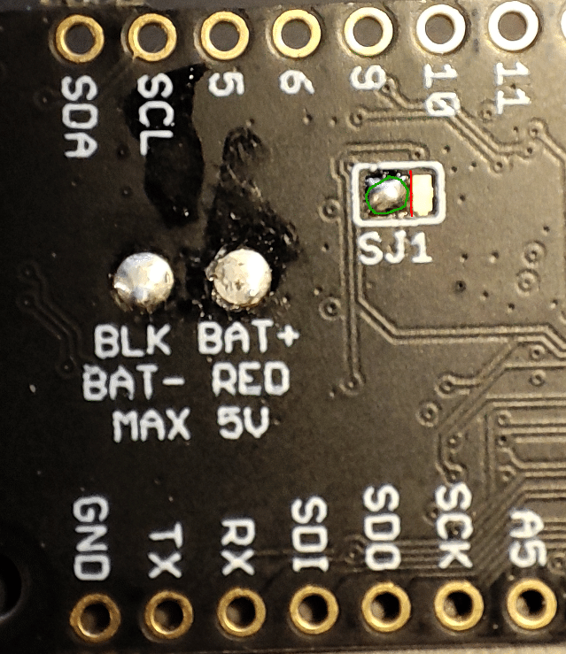
An external 3V battery can also be connected to the RTC via 2 solder points on the backside of the board. Here you can solder in an external 3V lithium battery och battery holder that is used to power the RTC while there is no power to the board. This is useful for systems where it can be tricky to set the time when the power has been lost.
When shipped the board is configured NOT to use these pads though, and in order to enable them you need also to modify the PCB jumper (SJ1) located near the pads.
The picture below shows the necessary modifications required. There is a short trace between the right pad and the center pad. This needs to be cut as shown by the red line in the picture. After that the leftmost pad must be connected to the center pad. The easiest way is to place a small solder blob over the 2 pads as shown in the picture under the green circle.
| Description | Value | Comment |
|---|---|---|
| Board Size | 50,80 mm x 22,86 mm x 3,20 mm | USB Connector protrudes ~1mm outside PCB |
| Main micro controller | RP2040 from Raspberry Pi | 133MHz dual core Cortex M0 |
| SPI | One SPI channel configured | |
| I2C | One I2C channel configured | |
| UART | One UART channel configured | |
| Analog inputs | 4 analog input channels | |
| FLASH Memory | 8MByte 133 MHz | |
| SRAM Memory | 264KByte | Divided into 6 banks |
| USB 2.0 controller | Up to 12MBit/s full speed | Integrated USB 1.1 PHY |
| JST Battery connector | 2.0mm pitch | |
| On board LiPo charger | 500mA standard charge current | |
| RTC | MCP79410 | Uses I2C0 (Wire) for communication |
| SD Card | One SPI channel used | Uses SPI1 to connect to the SD socket |