Challenger RP2040 WiFi6/BLE Datasheet
The Challenger RP2040 WiFi6/BLE is a small embedded computer equipped with a combined WiFi6 and BLE chip, in the popular Adafruit Feather form factor. It is based on an RP2040 micro controller chip from the Raspberry Pi foundation which is a dual core Cortex M0 that can run on a clock up to 133MHz.
This board is an evolution to the older Challenger RP2040 WiFi/BLE and comes with a couple of enhancements. First and foremost it adds WiFi6 to the mix which allows you to create battery powered WiFi based nodes that doesn’t run out of power.. (Well eventually it will, but it lasts much longer than with regular WiFi nodes).
The RP2040 micro controller is paired with a 8MByte high speed flash capable of supplying data up to the max speed. The flash memory can be used both to store instructions for the micro controller as well as data in a file system and having a file system available makes it easy to store data in a structured and easy to program approach.
The board can be powered from a Lithium Polymer battery connected through a standard 2.0mm connector on the side of the board. An internal battery charging circuit allows you to charge your battery safely and quickly.
The combined WiFi and BLE section on this board is based on the Espressif ESP32-C6 chip. The ESP32-C6 is based on the RISC-V processor core combined with a complex and powerful 2.4GHz radio block and 4MByte FLASH memory, making it a complete WiFi and BLE solution only requiring very few external components.

Short introduction to the board
PCB
The board is based on a popular form factor called “Feather” which is created and maintained by an American company called Adafruit. The entire specification for the Feather format is available here. The size of the PCB for the module is 50.80mm x 22.86mm but the entire module is a little bit bigger as the Type C USB connector protrudes about 1 mm outside the board.
Antenna
On the opposite end from the USB connector the WiFi antenna is mounted. When mounting the board into any enclosure you should make sure to keep stuff like cables and/or walls from the enclosure away from the antenna as much as possible. Anything mounted in the vicinity of the antenna will affect its performance.
Headers
On each of the longer sides of the PCB there are holes intended for soldering pin header connectors. If you don’t want to use connectors for some reason you can also solder a wire directly into the hole, making a permanent connection to your external device. If you go this way please make sure that the wires are fixed in place, otherwise vibrations can cause the wire to brake at the soldering point.
LED’s
On each side of the USB connector there is a small indicator LED placed. The LED which is marked CHG is the charge control indicator. This red LED will shine whenever the connected battery is being charged, and when the battery is fully charged the LED will turn off again. If you haven’t connected a battery to the board this LED will not come on at all.
On the other side of the USB connector there is a user programmable green LED. This LED is connected to pin D13 and can easily be controlled by the user program.
Finally there is a neopixel LED on the board. This is an RGB LED with intensity control, run by a single GPIO (D14/GPIO11) pin on the board. There are several good example libraries that can be used to drive this LED. An example can be found here.
Hardware details
Pins
The on board micro controller (RP2040) have a number of communication channels that have been routed out to the side (header connector) connectors.
- UART – One UART channel have been routed to the header pins (RX, TX). The micro controller have 2 UARTs, on this board the second UART is used for communicating with the WiFi chip.
- SPI – One SPI channel have been routed to the header pins (SCK, SDO, SDI).
- I2C – One I2C channel have been routed to the header pins (SCL, SDA).
- Analog pins – The micro controller have 4 analog input pins that all are available on the header pins (A0-A3).
- PWM – All pins can be used for PWM.
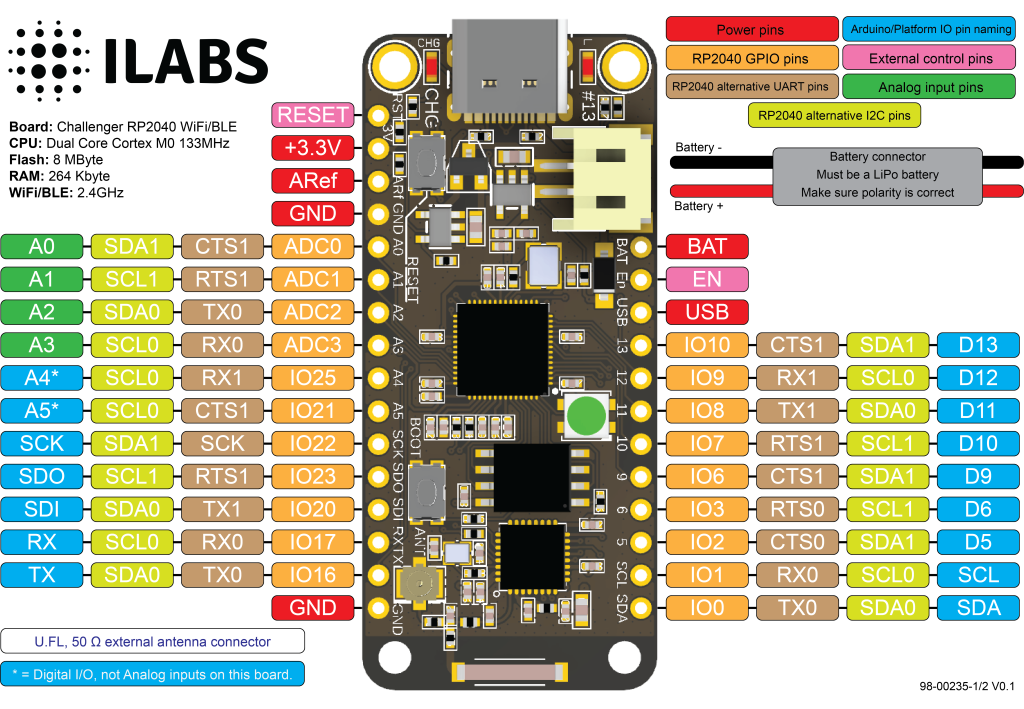
The pin chart below shows the placement of all pins and their respective functions. When working in an Arduino environment (or Platform IO) use the blue pins when writing your code and when working with CircuitPython use the orange marked pin assignments.
Power
The board can be powered from multiple sources. The most obvious way to run the board is by plugging it in to a USB cable and attach it to your computer. In this mode you can write software and test the board with all its functionality.
There is also a third way to supply the board. This way is more invasive and will disable the onboard 3.3V power regulator.
You will have to pull the EN header pin low and then supply your own 3.3V voltage on the 3.3V header pin. Please note that when disabling the onboard power regulator you will have to supply the 3.3V also when running the system on battery power.
Battery
As described earlier the board can be powered from a LiPo battery. The battery can be connected using a standard 2.0mm JST connector through the battery connector on the right side of the board or ff the battery is an integral part of the system that you are designing it is possible to connect the battery through the BAT pin instead.
Switching between the battery voltage and the applied USB voltage or external 5V is done seamlessly by the on board circuitry.
Charging of the battery is done by either connecting a USB cable or by connecting a 5V power source to the header pin marked USB on the board. If you do this make sure you connect your voltage through a 1A schottky diode to avoid any excessive current draw in the system when the two levels are slightly different.
Please note that providing external charger circuitry could destroy the internal charger on the Challenger board.
Network controller
Connection between MCU and ESP32-C6 WiFi controller.
The board uses the second UART (UART 1) of the MCU to connect to the ESP32-C6 as well as two GPIO pins that allows the RP2040 to reset and put the ESP32-C6 in flash mode. The pins used are as follows.
- GPIO4 acts as UART1 TXD
- GPIO5 acts as UART1 RXD
- GPIO19 is connected to ESP32-C6 reset and is active low (PIN_ESP32_RST in the arduino IDE).
- GPIO24 Is connected to the mode pin of the ESP32-C6. If it is pulled low at the same time the reset signal is going high the chip will enter flash mode (PIN_ESP32_MODE in the arduino IDE).
The ESP32-C6 is also connected via the second SPI channel to allow very high transfer speeds between the ESP32-C6 device and the RP2040.
SPI1 Pin usage:
- GPIO14 is the serial clock (SCK)
- GPIO12 is the serial data input (SDI)
- GPIO15 is the serial data output (SDO)
- GPIO13 is the ESP32-C6 chip select signal (#CS)
The ESP32-C6 SPI version of the AT command interpreter also uses an extra hand shake signal (HS) which is connected as follows.
- GPIO18 is the ESP32-C6 hand shake signal.
Network functionality
The ESP32-C6 device comes pre loaded with the ESP-AT interpreter already programmed into flash. This interpreter provides the system with everything from low level TCP/UDP functionality up to high level functions such as a on board integrated web server, MQTT server and client functions and much more.
Below is a more detailed list of functions found on the chip:
- Basic AT Commands – Basic control such as reset, check fw version etc.
- Wi-Fi AT Commands – All the functionality you need to scan, connect, disconnect, check RSSI etc.
- TCP-IP AT Commands – Low level TCP/UDP commands for sending and receiving data.
- Bluetooth® Low Energy AT Commands – All the functionality you need to create amazing BLE applications.
- MQTT AT Commands – A full featured MQTT server / client implementation.
- HTTP AT Commands – A set of high level HTTP commands that simplifies you applications.
- Signaling Test AT Commands – Commands for testing the RF performance of the product.
- Web server AT Commands – Setting up a webserver and serving HTTP-requests have never been easier.
The WiFi commands and TCP/UDP commands are supported by a few different libraries for different environments. For Arduino we recommend using the WiFiEspAT library which makes a very good job of mimicking the standard ESP32 Arduino WiFi stack and is very stable. There are others but we have not tested them all out.
If you would rather use Circuitpython, Adafruit has produced a library called espatcontrol that can be used without any modification to provide your board with network functionality. All of their examples work and you should have no problems getting them to work.
To support the built in MQTT functions we have created a thin Arduino support library that makes it a bit easier to get this up and running. You can find this library here. Please let us know if you have any problems with it or find any bugs.
Accelerometer
The accelerometer (MC3419) used on the board is the same as we used on our Bi2C- ACC board.
The MC3419 is a small form factor, integrated digital output 3-axis accelerometer with a feature set optimized for cell phones and consumer product motion sensing. Applications include user interface control, gaming motion input, electronic compass tilt compensation for cell phones, game controllers, remote controls and portable media products. The MC3419 features a dedicated motion block which implements algorithms to support “any motion” and shake detection, tilt/flip and tilt 35 position detection. Low power consumption and small size are inherent in the monolithic fabrication approach, where the MEMS accelerometer is integrated in a single-chip with the electronics integrated circuit. In the MC3419 the internal sample rate can be set from 0.5 to 2000 samples / second. The MC3419 supports the reading of sample and event status via polling but on this board the interrupt signal is not connected to the MCU.
The accelerometer is connected on the main I2C bus so it is extremely easy to start using.
Antenna options
The board is available with two different antenna options. The most common choice is to use the on board chip antenna that will give you very good coverage and ease of use. The second option is to buy the board with a U.FL connector and hook up an external antenna. This option is great if you need a little better coverage or if you really want to go overboard and hook up directional antennas and reach very long distances. The choice is yours.
| Description | Value | Comment |
|---|---|---|
| Board Size | 50,80 mm x 22,86 mm x 3,20 mm | USB Connector protrudes ~1mm outside PCB |
| Main micro controller | RP2040 from Raspberry Pi | 133MHz dual core Cortex M0 |
| SPI | One SPI channel configured | |
| I2C | One I2C channel configured | |
| UART | One UART channel configured | Second UART is for the ESP32-C6 chip |
| Analog inputs | 4 analog input channels | |
| WLAN controller | ESP32-C6 from Espressif | 160MHz single core RISC-V core |
| BLE controller | ESP32-C6 from Espressif | 4 MByte internal flash memory |
| FLASH Memory | 8MByte 133 MHz | |
| SRAM Memory | 264KByte | Divided into 6 banks |
| Accelerometer | MC3419 | |
| USB 2.0 controller | Up to 12MBit/s full speed | Integrated USB 1.1 PHY |
| JST Battery connector | 2.0mm pitch | |
| On board LiPo charger | 500mA standard charge current | |
| Onboard NEOpixel LED | RGB LED |